Terminal/Pin-Plug Manager
The Terminal/Pin-Plug Manager lets the user compile a list of terminals in the current project and allows you to select and edit the terminal information.
Accessed from:
The terminal strips in the current project are listed on the left side of the dialog in a tree view grouped by installation and location. To edit a terminal strip, select the strip's ID on the left side of the dialog so that it is highlighted. The terminal information for that strip will then appear on the right side of the dialog.
For each terminal in the strip, there is a series of columns with different types of information. Information about the terminal is in the center group of columns and information about the devices connected to the terminal appears to the left and right.
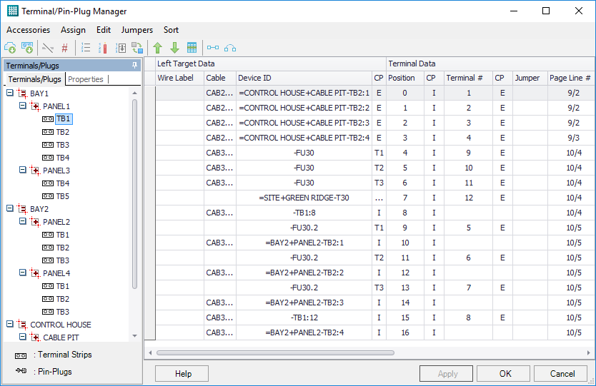
Target Data
| Setting | Description |
|---|---|
| Wire Label | Indicates the wire label of the wire connected to the connection point. |
| Wire Use | Indicates the wire use (layer) on which the wire is located. |
| Gauge, Color | Properties of the wire connected to the terminal. |
| Cable | If the terminal is connected to a cable, the cable device ID and conductor are identified here. |
| Device ID |
Indicates the device ID of the device to which the terminal connection point is connected. Once you create a spare terminal, you can define targets for it by clicking inside the Device ID field on the Left Target or Right Target side of the terminal. A browse button will appear in the field. Select this button and the Define Target dialog will open letting you define the targets for the terminal. |
| CP | Indicates the connection point text of the device to which the terminal connection point is connected. |
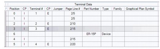
Terminal Data
| Setting | Description |
|---|---|
| Position | Indicates the position of the terminal in the terminal strip. |
| CP | Indicates a connection point on the terminal symbol and the designation of the connection point. |
| Terminal # | The terminal number assigned to the terminal. |
| Jumper | If a jumper connection exists, the terminal number of the terminal to which the jumper connects will be listed. |
| Page Line # | Indicates the line number on which the terminal is placed. |
| Part Number | The part number assigned to the terminal. |
| Family | If the terminal is part of a device family, it will be indicated here. This is particularly useful for devices such as 3-tier terminals to be assigned to a family. |
| Graphical Plan Symbol | The symbol that will represent the terminal in a graphical terminal plan. |
When you select a terminal on the right side, you can also see this information in the Properties tab on the left side of the dialog. You make assignments in the Part Number(s) field in this tab. If you select multiple terminals you can make the same assignment to them all.
Terminal Editing Functions
| Setting | Description |
|---|---|
| Change Terminal Order |
Change the order in which the terminals are listed in the terminal manager by using the up and down arrow buttons in the terminal manager toolbar. Select the desired terminal and then select the up or down arrow button to move it up or down the list. You can also change a terminal's position by
dragging it and dropping it in the list.
If you wish to actually change the terminal numbers to reflect
the order in which they are listed, use the
Edit > Renumber Incrementally function.
|
| Accessories > Insert Device |
Inserts a part number into the terminal strip that represents an additional component of the terminal strip such as a spacer or end block. By inserting such a device that might not appear in the schematic, its part number will be included in the bill of materials and it can also appear in the graphical terminal plan. After the Select Part Number dialog appears, select the desired device part number by double-clicking on it. Selected part numbers appear in the lower area of the dialog. Select OK to assign the part number. The part number will be included in the terminal strip after the selected terminal. |
| Accessories > Insert Spare | Inserts one or more extra terminals into the selected terminal strip. Displays the Insert Spare dialog letting you define quantity and type of spare terminals to insert. |
| Accessories > Delete Device & Spare | Deletes a device or spare terminal that you have added to a terminal strip. You will be asked if you wish to delete the items. Select Yes. The selected items will be removed from the strip. |
| Assign > Cable |
Assigns the conductors of a cable to a group of terminals. Cables assigned in the terminal manager will be added to the schematic drawing automatically. The Insert Symbol by Name dialog will appear prompting you to select a cable symbol. You can select a symbol from the list, enter a symbol name in the Name field, or you can search for a symbol by entering part of its description in the Description field and selecting the Search button. Any symbols with descriptions that contain the search term will be displayed. When you have selected the symbol, select the Place Symbol button. The Device Properties dialog will appear. Enter a device ID for the cable. If desired, use the Search button to assign a part number. You must also select a device family for the cable in the Family field. This determines the number of available conductors in the cable. Select OK to continue. The Device Usage Chart dialog will appear. Select OK to continue. The Device Properties dialog will re-appear. Select OK to continue. The Cable Text dialog will appear. Here you can enter descriptive texts related to the cable. Enter any desired descriptions and select OK to continue. The cable conductor assignments will be indicated in the Cable column of the terminal manager. The cable will also appear in the schematic diagram. |
| Assign > Delete Cable | Removes the selected cable. |
| Assign > Part Number | Assigns a part number to one or more terminals. When
you view terminals in the terminal manager, any assigned part number will be
will be listed in the Part Number column. The
Select Part Number dialog will appear listing the available
terminal part numbers.
Select the desired part number by double-clicking on it. Selected part numbers appear in the lower, Selected Items area of the dialog. Select OK to assign the part number. The selected part number now will be listed in the terminal manager. It also will be shown in the schematic, bill of material, etc. |
| Edit > Delete Spare Target | Removes the selected spare target. |
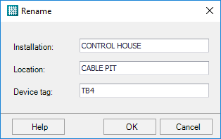
| Edit > Rename | Renames the terminal strip of any selected terminals. This has the effect of moving the terminals to another strip. |
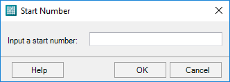
| Edit > Renumber Incrementally | Select the lowest number to be assigned to the selected terminals. |
| Edit > Renumber by Potential | Renumbers terminals using the order of the potentials connected to each terminal. |
| Edit > Swap Targets | Switch terminal targets from the left side to the right side of the terminal manager. The target data will change positions from one side of the terminal to the other. |
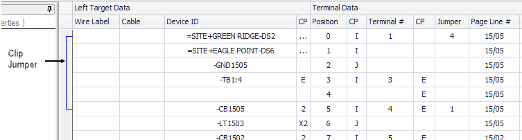
| Jumpers > Clip Jumpers | Designates two terminals on the same strip as being connected with a clip jumper. The terminal must be one that can be legitimately connected to another terminal or terminals, i.e., there must be a direct connection between them in the schematic. The connection will be indicated by a blue line to the left of the data columns that connects the two terminals. |
| Jumpers > Wire Jumpers | If two terminals have been connected by a clip
jumper and you wish to return to a wire connection, you can use the
Wire Jumper function.
The terminal you selected will appear in the From column and the terminal it connects to will appear in the To column. You must specify which connection point on each terminal should be connected. For each terminal you can only select one connection point, either on the left or right side. When you click in the Left or Right fields, the available connection points will appear in a drop-down list. When you have selected the desired connection points, select the OK button. The blue clip jumper line will be removed from the left column and the target columns will be updated with the wire connection. |
| Sort > By Terminal # | Sort in numerical order by terminal number. |
| Sort > By Part Number | Sort terminals alphanumerically by part number. |
| Sort > By Potential | Sort terminals by the potential to which they are connected. |
| Sort > By Position | Sort terminals by position number. Select submenu for left or right side. |
| Sort > By Page Line | Sort terminals by page and line number position. |
| Sort > By Target Device ID | Sort alphabetically by the target device ID. Select submenu for left or right side. |
| Sort > By Wire Label | Sort terminals alphanumerically by wire label. Select submenu for left or right side. |
| Sort > By Wire User | Sort terminals by wire use column. |